



© 2012 Momus CNC
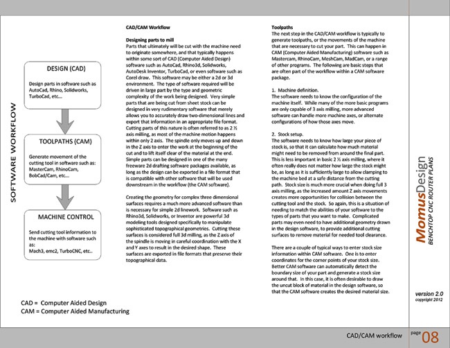
The Momus CNC construction manual covers
the complete fabrication and assembly of the
machine that is shown throughout this
website, as well as a range of related
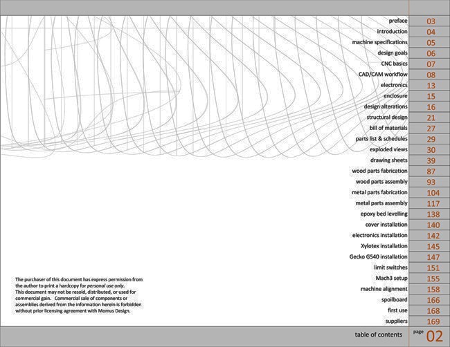
information. The image to the right shows the
table of contents and the extensive quantity of
information contained within the manual, from
basic information on CNC principles, part
drawings, assembly of the machine, to lists of
material and software suppliers.
Construction Manual
In addition to complete information required to
build the machine, the construction manual
contains auxiliary information such as basic
principles of CAM (Computer Aided
Manufacturing) software, and other knowledge
which will be helpful for the operation of the
finished machine.
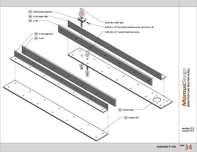
Exploded-view drawings show the assembly
and part relationships of all mechanical
sub-assemblies. These drawings also provide
part names and numbers, which are keyed to
orthographic drawings of each individual
component. Exploded-view drawings are
provide for both the fabricated metal
mechanical components, as seen here, as well
as the wood base. In addition to these
drawings, extensive photographic images
illustrate each assembly step.
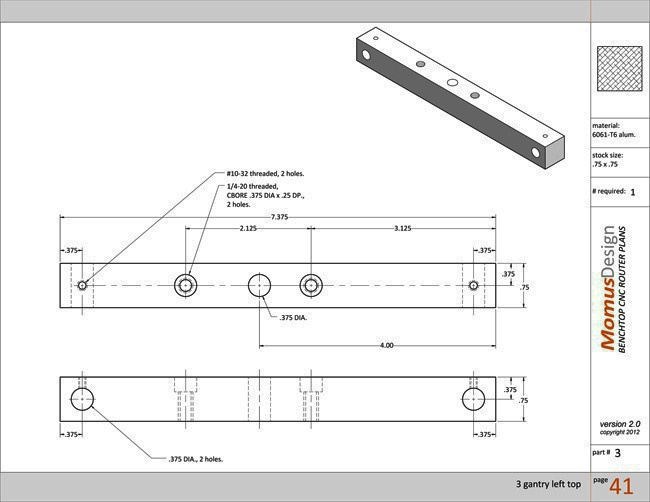
All fabricated components are documented
with multi-view orthographic drawings. These
orthographic drawings are accompanied by a
3d drawing of each part, shown oriented in the
position that it will be assembled onto the
machine. Each of these drawing sheets also
list the quantity required of each part, the
material from which it is to be made, and the
size of stock from which it is cut.
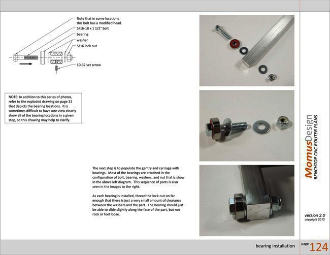
Each step of the machine construction,
including the fabrication of parts, their
assembly, wiring and installation of
electronics, and final mechanical adjustment,
is documented with extensive photographs
and written descriptions. In addition to these
photographs and descriptions, drawings are
provided as necessary for even greater clarity.
These include both exploded drawings, as
seen in the image to the right, as well as
wiring diagrams.
ERRATA
All current known errors in the plans are listed HERE.
All current known errors in the plans are listed HERE.


